Projects / Alouette II rear transfer gearbox
Alouette II rear transfer gearbox
The gearbox
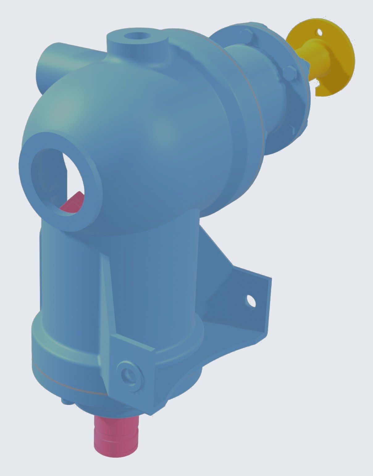
On the Alouette II helicopter, this gearbox takes power from the main rotor output to the tail rotor. It is a simple bevel gear reducer. It turns the drive by about 95 degrees and brings 1,500 rpm at the input down to about 1,200 rpm at the output. The output shaft is hollow, so that the tail rotor pitch control rod can run through it.
The brief
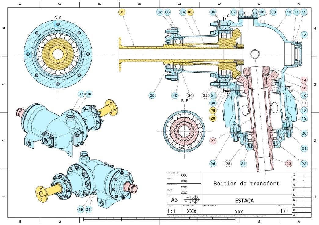
Each pair of students received its own bearing sizes, different from the original drawing, and had to redraw the whole gearbox around them in CATIA 3DEXPERIENCE. The rules were the same for everyone.
- Each gear sits on its shaft with a flat face and a short centering, held by 6 to 8 M4 screws. The clamping carries the torque, the screws must not work in shear.
- Same isostatic bearing arrangement as the original.
- Mounting points on the helicopter kept where they were, so that the new gearbox still fits existing aircraft.
Our set came with 6005 ball bearings and NU 2306 ECML roller bearings, and the bolt circle of the output flange had to be a driving parameter. We split the work by equivalence class in a shared workspace, each of us drawing our own subassembly. I took the output side and the main housing.
What we changed
Shafts first
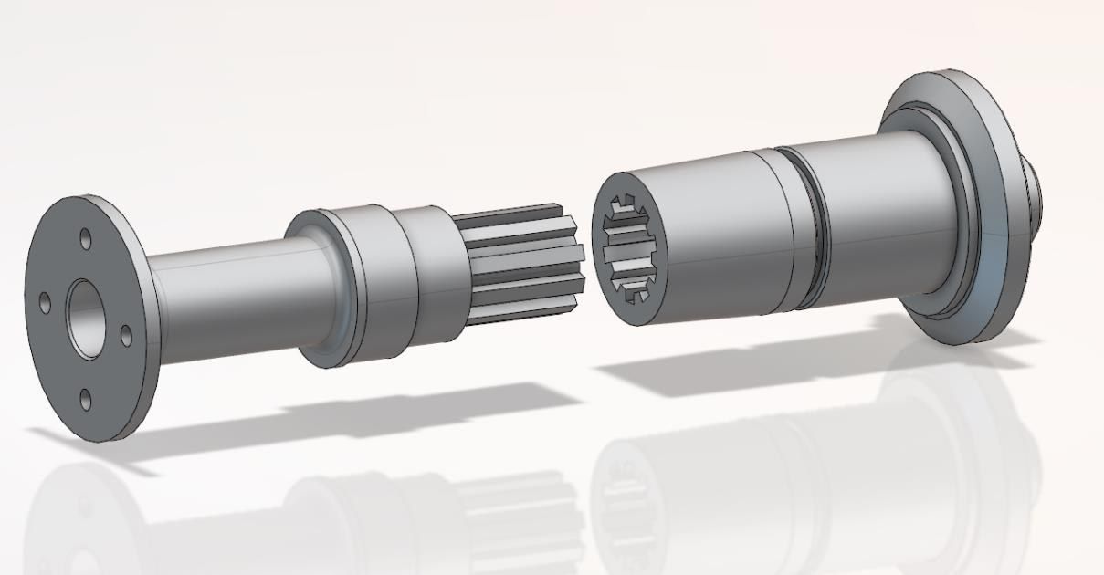
We drew the shafts before anything else, since every other part depends on them. The first version of the input shaft could not take its bearings. One shoulder became a circlip, another a spacer. The output shaft was split in two, with splines carrying the torque, so that it could be assembled.
Gear to shaft link
As required, each bevel gear now sits on a flat face with a short centering. We added a tenon to the gears, so that the shear load goes through it instead of the screws.
One parameter for the bolt circle
A single assembly parameter drives the bolt circle across the three parts it touches, the output housing, its flange and the shim. It is bounded between 57 and 100 mm, the lower bound being set by the size of the screw heads.